


A Liquid Sodium Simulation of the α - Ω DynamoA Proposal to the NSF for Continuing Support of a Laboratory Simulation ofThe α - Ω Accretion Disk Dynamo that Powers AGN& Creates the Magnetic Fields of the UniverseSTIRLING A. COLGATE, HOWARD F. BECKLEY, JAMES C. WEATHERALL,& VAN D. ROMERO, Physics Dept., New Mexico Institute of Mining & Technology, Socorro, NM 87801 (Submitted to the National Science Foundation 22 September 2000) Project SummaryA liquid sodium analog experiment is proposed as a proof-of-principle of the α - Ω dynamo. The successful demonstration of the α - Ω dynamo will have important astrophysical significance. A substantial energy component of the universe appears as magnetic energy filling the walls and voids, and is particularly evident in AGN in galactic clusters. The origin of this field is not explained. Assuming that the major free energy of the universe progresses through galaxy formation to massive galactic central black holes, the black-hole accretion disk provides a natural α - Ω dynamo which can process black-hole binding energy into helical, force-free magnetic field. The experiment is designed to simulate the type of field deformations produced by Keplerian rotation and the collision of stars with the accretion disk. Other applications of the α - Ω dynamo include the generation of magnetic fields in stars from deep convection and in neutron stars during supernova collapse. With seed money from the NSF and LANL, the design and major construction of the experiment for the Ω-Phase, and two-thirds of the electronics have already been done. Initial flow visualization experiments have been performed using water to demonstrate the Ω-flow field and the α-deformation required by the dynamo. The expected positive gain in the experimental apparatus is supported by a kinematic dynamo code at LANL. The proposed new work is to use the apparatus to demonstrate the α - Ω dynamo using a conducting fluid, liquid sodium, as the fluid medium. The first phase of the experiment is designed to show a multiplication of ~ × 20 of the toroidal field from an initial bias poloidal field, and the second phase, a positive dynamo gain. Confidence in the engineering feasibility and safety is gained from recent successful liquid-sodium experiments at Riga and Karlsruhe on a different class of α2-dynamo (not applicable to accretion disks). However, the scale and cost of the proposed α - Ω dynamo is much different from those experiments, which were conducted in facilities left over from fast reactor coolant work. For example, there is a vast difference between using sodium at 600 C as a fast-reactor coolant and using sodium at 110 C as in this experiment. Safety is a paramount concern in this project. The experiment itself will be reviewed and conducted at a major high explosive testing facility, the Energetic Materials Research and Testing Center (EMRTC), located at the New Mexico Institute of Mining and Technology. 1. ABSTRACTThe dynamo within the accretion disk forming the massive, central black hole of nearly every galaxy almost certainly converts this black hole binding energy, the major free energy of the universe, into the previously unrecognized form of intergalactic magnetic field. With equal conviction this ubiquitous massive dynamo in all AGN must be an α - Ω dynamo. We propose to demonstrate in the laboratory that such a dynamo works. 2. PLANS FOR THIS PROPOSALWe plan to test first the now constructed Ω-Phase apparatus of a liquid sodium dynamo experiment. Here, the differential winding, the Ω-flow, is Keplerian flow in the disk, Ω ∝ R-3/2, meridional circulation in stars, Ω ∝ R-x, and Couette flow in the experiment, Ω ∝ R-2. We plan to measure first the expected large multiplication, ~ × 20, of an initial bias poloidal field, into toroidal field by Couette flow alone in the liquid sodium. This multiplication is the first step of the α - Ω dynamo (Parker 1955; Parker 1979). We plan to continue with constructing the driving mechanism for the α-deformation in the same apparatus, and test the α-Phase leading to dynamo gain. We expect to achieve positive gain within the design limits of the strength of the containment vessel and power of the experiment. The α - Ω dynamo is fundamental to most astrophysical dynamos. We believe that this dynamo is formed because of (1) the differential rotation within the Keplerian disk, the Ω-deformation, and (2) the plumes produced by star-disk collisions. These plumes are ejected to large heights above the disk, most probably give rise to the broad emission lines (Zurek et al. 1994) and give rise to the α deformation. Pop III stars are a small mass fraction, ~ 10-3 to -4, of the pre-galactic mass, but their predicted collisions with the disk are frequent enough to drive the necessary helicity or α-deformation of the α - Ω dynamo. In addition to this translation of matter and magnetic flux to large heights above the disk, we have predicted, and now confirmed with a laboratory water flow visualization experiment (Beckley & Colgate 1998) how expanding plumes in a rotating frame, rotate (in the same direction every time) differentially through a finite angle, ~ π/2 radians, relative to the rotating frame. This finite, coherent, rotation angle forms the basis for the α-deformation, or helicity, of the α - Ω dynamo. The plumes are produced by driven pulsed jets in the experiment. They occurs naturally within the postulated black hole accretion disk dynamo by star-disk collisions, and similarly from convective plumes in stars and planets and even in the neutrino-heated halo of neutron stars during the supernova explosion.
The prior verification of plume rotation is central to the feasibility
of the experiment. The verification of the rotation of the toroidal
magnetic flux entrained within the plumes is similarly crucial to the
dynamo. We plan to measure this rotated flux in the experiment
under conditions less extreme than would predict positive dynamo
gain. Similarly, the differential rotation of the Ω-deformation is created in the laboratory experiment as
stable Couette flow between two rotating cylinders. The advantage of
stable Couette flow in the laboratory is the greatly reduced friction
and hence reduced power required for reaching a given velocity and
hence, a high value of magnetic Reynolds number, Rm,Ω ≅ 120 in the experiment. We plan to
measure this multiplication first.1
When all the above parameters of the experiment have been measured and
understood, we plan to increase the power, velocities, and
magnetic Reynolds numbers to the point of positive dynamo gain. Finally we are interested in extending the theory of the α - Ω dynamo in the context of astrophysics. Already at Los Alamos, in conjunction with the initiation of this experiment, we are developing the theory of (1) the formation of the accretion disk leading to the galactic black hole via Rossby vortices, (2) the formation of the α - Ω dynamo within this disk, and (3) the formation of the force-free helix that distributes the magnetic energy and flux throughout the universe. However, this experiment is hosted by NMIMT, where also the VLA and VLBA share joint faculty appointments. It is fair to say that almost every observation in the radio spectrum depends upon synchrotron emission from some object with a magnetic field of unknown origin. One of us, Prof. Weatherall shares a joint appointment with NRAO. This offers the opportunity for a much needed link between theory, observation, and experiment. We plan to pursue calculations that apply the α - Ω dynamo to the formation of the magnetic field of neutron stars during their supernova phase of their formation. Supernova calculations are unique for this endeavor in that the input of kinematic dynamo calculations can come directly from supernova modeling calculations where large-scale convective plumes have been shown to be fundamental to the explosion mechanism (Herant et al. 1994).
3. RESULTS FROM PRIOR NSF SUPPORT, re: 99-00661With $100k initial seed money from NSF and $30k from LANL, a full mechanical design of the Liquid Sodium α - Ω Dynamo experiment has been completed, Fig. 1, as well as the construction of the rotating parts, Fig. 3. This system, designated the Ω-Phase, is designed to produce the critical magnetic Reynolds number Rm,Ω ≅ 120 in Couette flow in liquid sodium.
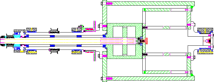
Figure 1: Figure 1 shows a detailed design
drawing of the rotating components of the the Ω-Phase of the Liquid Sodium α - Ω
Dynamo experiment. By comparing Figs. 1 & 2 the labeling of
the various components can be compared and identified in the two
drawings. The main cylinder of radius, R0 = 30.5 cm
rotates between two bearing mounts with three bearings. In the Ω-Phase no plume piston, or hydraulic drive is shown,
even though the constructed aluminum parts of Fig. 2 show the
port plate and two ported reservoir plenum cylinders. These parts are
necessary to define the plume end of the Couette flow annular
space.
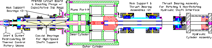
Figure 2: Figure 2 shows shows the design
drawing of both the rotating components as well as the plume drive
mechanism of both the α- and Ω-Phases of the Liquid Sodium α - Ω Dynamo experiment. The primary drive shaft, belt pulleys,
and electric motor are not shown, but have been designed, components
purchased, and partially constructed.
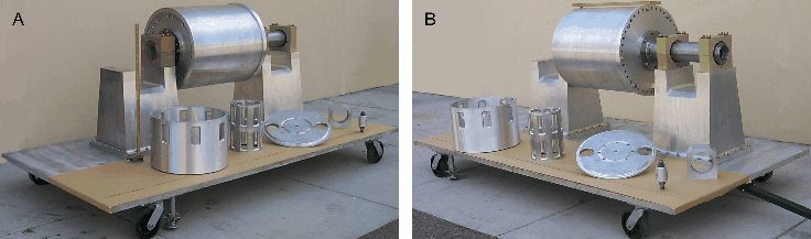
Figure 3: Figure 3 shows the constructed
parts the Ω-Phase of the Liquid Sodium α - Ω Dynamo experiment mounted on the bearings and
supporting pedestals. Also shown is the port plate and two ported
reservoir plenum cylinders and the inlet & outlet recirculating
oil rotary unions. The primary drive shaft, belt pulleys, and
electric motor have yet to be added.
Figure 1 shows a detailed design drawing of the Ω-Phase of the Liquid Sodium α - Ω Dynamo experiment. The functions of the components of Fig. 1 can be recognized from the sub-captions of Fig. 2. These describe the design of the entire apparatus including the main rotating cylinder, the internal construction of the rotating components, the plume drive piston, the port plate, and ported reservoir plenum cylinders. The oscillating hydraulic drive for the jet- plume production is a hydraulic cylinder driven by a secondary source of power. Figure 3 shows the constructed rotating components of the Liquid Sodium α - Ω Dynamo. The plume port plate and reservoir plenum cylinders are shown yet to be mounted internally. The plume drive piston is not constructed in this phase. The plume port plate is supported by both reservoir plenum cylinders for greater rigidity. The rotating drive components of the experiment are not yet mounted on the bearing supports. The massive bearing supports and base plate are surplus materials. Their their large mass, ~ two tons, is designed to reduce the rotating vibration amplitude. The oscillating hydraulic drive mechanism for the jet- plume production is not constructed, awaiting the α-Phase of the experiment.
The α-Phase, Fig. 2 with the addition of the drive mechanism
has been designed to produce the pulsed plumes for the α-
deformation. The helicity produced by the plumes in a rotating
frame then permits the measurements of dynamo gain. The
centrifugal stress in the vessel walls is designed to be 1/3 of
the yield strength of the rotating chamber. (The total running
time of the apparatus at modest speed should be no more than
several hours and at extreme high speed only tens of minutes.) The
equipment for the rotating power has been identified and reserved
from surplus. The HTD belt-drives, bearings and bearing mounts
for both the low-speed drive tube and high-speed drive shaft for
power transmission have been purchased, constructed and
assembled. The principle components of the hydraulic system
necessary to produce the plumes have been designed, identified and
reserved. Similarly the recirculating heated-oil system used to
liquefy the sodium through heat transfer in the inner cylinder and
possibly cooling has also been designed. We have designed the
high-pressure oil lubrication system used for the dynamo
main-support bearings and for the hydraulic ram thrust bearing
assembly. All components for this system have been reserved from
surplus.
Due in part to in-kind contributions from the Research
Division of NMIMT, a new laboratory space for the design,
development and construction of the experimental dynamo and its
electronic instrumentation has been set up. A new computer for
instrumentation control and data acquisition has been purchased
and set up. Los Alamos National Laboratory has contributed funding
to complete the construction of the Ω-Phase. This will
particularly help in validating the kinematic vector potential
dynamo code for use with astrophysical dynamos. A web site has
been established. (Please see http://physics.nmt.edu/~dynamo/.) The electronic instrumentation has been designed and constructed with the help of undergraduate students, Clint Ayler and Manuel Jaramillo. It has been designed to measure the pressures, temperatures and magnetic fields at various locations of the rotating fluid and to be converted for digital transmission to the computer. In total 128 sensors are designed to be monitored at ~10 MHz data rate from a rotating system with a centrifugal acceleration of ~1000 g at the sensors and ~200 g at the electronics. The sensors have been identified, purchased and verified. The data aquisition, transmission, and interconnection with the computer has been designed, and bread-boarded as well. The design of the circular printed circuit is now in fabrication. The magnetic instrumentation uses small, single-axis Hall effect detectors without internal gain (18 Hall sensors in the Ω-Phase and 108 in the α-Phase). These magnetic sensors have sufficient dynamic range to measure from the earth's field, 0.2 G to the expected transient, back-reaction saturation field, 15 kG, if positive gain is achieved. These miniaturized detectors are assembled into three-axis packages and arranged in linear and matrix arrays. Included with the Hall detectors are the associated multiplexers for power distribution and signal collection, linear and log operational amplifiers, analog to digital converters, and digital transmission through capacitative slip-rings to the computer, now tested and bread boarded. This instrumentation configuration will allow for trouble shooting, diagnostics, and calibration procedures to be established prior to the sodium experiments. This instrumentation system has been designed to ensure that the following can be observe in the rotating frame: 1) The temperature of the oil and of the sodium at several locations to ensure that the sodium is liquefied and not overheated by friction. 2) The pressure at 5 radii at the end wall to derive and interpret the Couette flow rotation profile. 3) The magnetic field in 3-axes at 6 locations radially within the rotating fluid in order to measure the poloidal and toroidal field, the Ω-Phase. The toroidal multiplication, Btoroidal/Bpoloidal ~ 10 to 30, is the Ω-effect. 4) The magnetic field in 3-axes in a 5 × 6 = 30 matrix array located opposite one plume at the end-wall. This allows a reconstruction of the field topology (rotation) produced by the plumes. The poloidal component of this field distribution, derived from the plumes is the helicity or α-effect. This instrumentation is to be constructed just for the α-Phase. In addition, in the stationary frame there are provisions to monitor 15 additional detectors of temperatures, pressures, and the quadrupole bias field while the rotating experiment is in progress. In total, the instrumentation was designed to determine: 1) The separate partial toroidal and poloidal multiplications. 2) The combined partial dynamo gain. 3) The positive exponentiating gain.
4) The saturated dynamo field configuration if positive
gain is achieved. In summary, the mechanical design of the experiment is completed. A working laboratory for the experiment is established. The major fraction of the mechanical equipment has been constructed and purchased. We have designed, tested, bread-boarded, and initiated construction of the diagnostic sensors and electronics to instrument the experiment. The experiment has been modeled with realistic experimental values of magnetic Reynolds number. The plume rotation has been experimentally verified. These allow the prediction of: 1) a large measurable signal of the Ω- and α-effects separately at well below 10% of the design stress and power. 2) partial, (negative) dynamo gain at 10% of design stress and power.
3) positive gain at ~1/3 the yield stress of the
vessel and less than the limiting power. The following paper has been submitted for publication.
The following talks have been given:
In addition talks have been given at: The New Mexico Symposium,
NRAO, 10/99; NMIMT colloquium, 12/1999; Aspen Center For Physics,
winter work shop 1/31/2000; Cornell Univ. colloquium, 3/10/2000;
SLAC, colloquium, 4/18/2000; APS Meeeting, LongBeach, 4/29/2000;
Aspen Center For Physics; 6/2000. In addition the theory and astrophysical motivation for the experiment has been substantially advanced supported by Los Alamos National Lab. We, (Colgate, Hui Li, Vladimir Pariev of LANL and R. Lovelace of Cornell ) believe we have solved five major problems that when linked create a causal picture of the flow of the major free energy in the universe. The α - Ω dynamo is only one, but crucial step in this sequence. Starting with the collapse of a galactic mass Lyman-α cloud, the baryonic fraction forms, with cooling, a flat, co-rotating disk. We are presently calculating how tidal torquing separates angular momentum and mass to produce the "flat" rotation curve mass distribution, Minterior ∝ 1/R. We believe we have solved a long standing problem of the hydrodynamic transport of angular momentum in accretion disks, the α-viscosity problem, by the excitation by radial pressure gradients of co-rotating Rossby vortices. The excitation of Rossby vortices depends upon entropy conservation and hence thickness, which in turn with the "flat" rotation mass distribution predicts the previously enigmatic 108 Mʘ black hole. With the theory and experiment of this proposal we have predicted the α - Ω dynamo in this disk, which, when saturated, converts all the free binding energy of the black hole to magnetic energy. We have calculated how this magnetic energy naturally forms a large, force-free helix, filling the inter-galactic space in the walls with evidently, stable, force-free magnetic flux. Because of this stability we predict that the configuration lasts a Hubble time in the walls and voids. We are now calculating how this force-free flux partially reconnects and slowly over a Hubble time, converts the magnetic energy to the extragalactic cosmic ray spectrum. The short loss time of the CRs from the walls to the voids avoids the GZK cut-off, and the energy required is supplied by the magnetic field energy from the BH binding energy through the α - Ω dynamo of every forming galaxy. Papers that have been written or submitted on these topics are: Lovelace et al. 1999; Colgate & Buchler 1999; Li 2000; Colgate & Li 1997.
4. BACKGROUND4.1. Astrophysics BackgroundThe constraint of the conservation of energy and momentum are the final tyrannies in astrophysical theories. Dark matter has allowed us to tinker with gravity, and the universe is an infinite sink for angular momentum. Entropy can always be dispersed at 3 deg K in the BB radiation or at 2 deg K in the neutrino background (good luck). Finally magnetic flux can be dissipated by reconnection, but it can only be generated astrophysically by a dynamo (with caveats).
There have been hundreds of papers and dozens of reviews on the origin
of galactic and extragalactic magnetic fields, but almost universally
the magnitude of the energy and of the flux required has not been
emphasized; yet a dynamo produces only magnetic flux and magnetic
energy (see Kulsrud 1999; Zweibel & Heiles 1997; Parker 1979;
Ruzmaikin 1989; Moffatt 1978; Krause & Beck 1998; Weilebinski
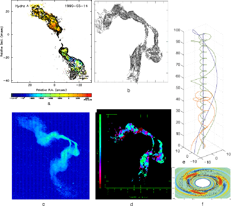
1993). In addition, flux and energy are seldom emphasized in the observations (see reviews by Miley 1980; Bridle & Perley 1984, Kronberg 1994 and the observations themselves, e.g. Perley et al. 1984; Taylor et al. 1990; Taylor & Perley 1993; Taylor et al. 1994; Eilek et al. 1984; Kronberg 1994). However, the magnitude of the implied fluxes and energies, ~1060 erg, in galactic cluster sources as well as ~1061 erg in field AGN outside clusters in the radio lobes, are so large, ×104 and ×106 respectively compared to these quantities within standard galaxies, that their origin requires a different source of energy and a different form of the dynamo than a galactic one. The difficulties associated with a primordial origin of the field is recently augmented and reviewed by the analysis of Blasi et al. 1999, leaving only an α - Ω dynamo in a BH accretion disk dynamo as the plausible explanation. Figure 4 shows the rotation measure maps of the AGN in the Hydra Cluster, (Taylor & Perley 1993) and of the cluster 3C75 (Eilek et al. 1999). These maps show the immense dimensions, 50 to 100 kpc, over which the fields are coherent in field direction and the underlying polarization in the case of 3C75. The absolute value of the fields, 33 μG in the case of hydra and 10 to 20 μG in the case of 3C75 throughout the volume of these dimensions leads to the extraordinarily large total energies.
Figure 4: Figure 4(a) shows the Faraday
Rotation map in color overlaid upon the emission contour map of the
Hydra Cluster (Taylor & Perley 1993). Figure 4(b) shows the
polarization of the emission ,Fig. 4(c), resulting in the Faraday
rotation map, Fig. 4(d), of the AGN in cluster 3C75 (Eilek et
al. 1999). The total emission from minimum energy arguments leads to
× 10 to 30 greater field energy than the Faraday
rotation measure. Figure 4(e) shows the force-free helix produced by
the boundary condition of the Rossby vortex accretion disk,
Fig. 4(f) (Colgate & Li 1998).
These energies are much larger than the binding energy of galaxies ×102 (including the dark matter) and the fluxes are ×103 greater than the magnetic flux of the galaxy times the winding number of the galaxy in a Hubble time, ~50 turns. However, the free binding energy of the black hole, ~1062 erg, and the winding number of the disk forming the BH of nearly every galaxy is the feasible source of both this flux and energy. The conversion of nearly all this energy, ~90% to 95%, into a form of magnetic energy that is not rapidly (in an Alfv'en time) dissipated into an observational form is the challenge of the physics of the accretion disk α - Ω saturated dynamo. Furthermore, the distribution of this magnetic flux and energy throughout the universe is an equal challenge. We believe this requirement can only be met by the dynamo creating a cylindrically symmetric force-free magnetic field, a helix. The dissipation of this extragalactic field and the remaining 5% to 10% of the magnetic energy in the form of the AGN spectra is the challenge of understanding the plasma physics of reconnection and the consequential acceleration in force-free fields. The discovery of this missing magnetic energy is the challenge to observations. Together this would explain the missing BH luminosity (Richstone 1998; Krolik 1998), the fraction we do observe as the AGN phenomena, and the magnetic fields of the universe. Finally the reconnection of these extragalactic force-free fields during a Hubble time is the reasonable explanation of the extragalactic cosmic ray spectrum. Only the α - Ω dynamo, when saturated, has the potential for transforming the accretion disk kinetic energy into an axisymmetric force-free field configuration. Finally the winding number or number of turns of the inner most orbits of the accretion disk is so large in the lifetime of the disk, ~1012 turns in 108 years, that the smallest dynamo gain per turn, a small fraction of 1012, leads to saturation in a short time. This high, near infinite gain avoids the question of the origin of the seed field. This view of the dominant role of magnetic energy in the universe is presented in Colgate & Li 1997; Colgate & Li 1998.
4.2. The Physics and How an α - Ω Dynamo Works
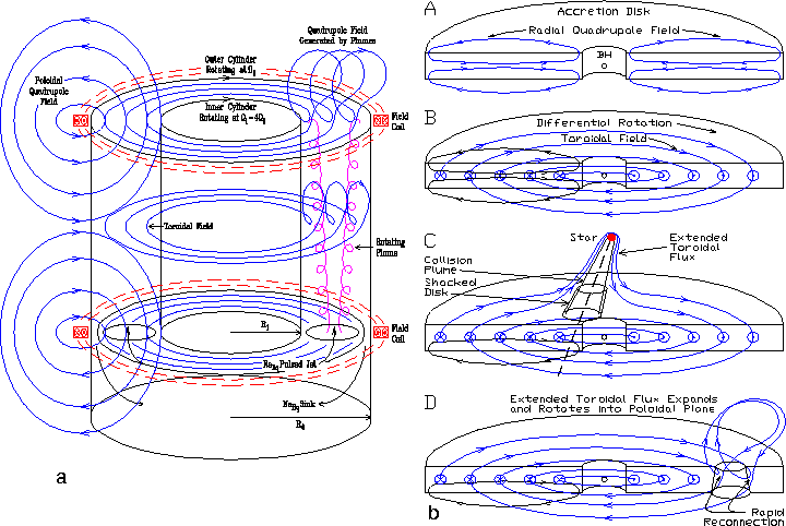
Figure 5: Figure 5(a) shows the sodium
dynamo experiment in comparison to the accretion disk dynamo of
Fig. 5(b). In both cases differential rotation in a conducting
fluid wraps up an initial radial field component into a much stronger
toroidal field. Then either liquid sodium plumes driven by a pulsed
jet or star-disk collisions eject and rotate a loop of toroidal flux
into the poloidal plane. Resistivity or reconnection merges this new
or additional poloidal flux with the original poloidal flux leading to
dynamo gain.
Figure 5(a) shows how the α - Ω dynamo works in the Liquid Sodium Dynamo experiment and Fig. 5(b) shows how the α - Ω dynamo works [in the accretion disk forming the galactic black hole]. Differential rotation is established in the liquid sodium, [ionized accreting matter], between two rotating cylinders as Couette flow, Ω ∝ 1/R2, by driving Ω1 = 4Ω0 where R0 = 2 R1 [and Keplerian, Ω ∝ 1/R-3/2, around a central mass, the black hole]. This differential rotation wraps up the radial component of an initial poloidal, quadrupole bias ~100 G field made with coils [or Fig. 5(b(A)) an infinitesimally small, < 10-19 G field from density structure at decoupling]. The resulting toroidal field is stronger than the initial poloidal field by Btoroidal/Bpoloidal = nΩBpoloidal is the number of turns. This multiplication factor becomes nΩ ≅ Rm,Ω/2π where the magnetic Reynolds number Rm,Ω = Ω0R02/ηNa and ηNa is the resistivity of liquid sodium or [for the disk, ionized plasma, Rm,Ω = Ω0Hdisk2/ηplasma where the height of the disk, H0 >> R0]. Then a driven pulsed jet [or a collision with the disk by a star, Fig. 5(b(C))] causes a plume to rise towards the end plate [or above the disk] with displaced toroidal flux forming a loop of toroidal flux. The radial expansion of the plume material causes the plane of this loop to untwist or rotate differentially about its own axis relative to the rotating frame so that the initial toroidal orientation of the loop is transformed to a poloidal one, Fig. 5(b(D)). Resistive diffusion in liquid sodium metal [or reconnection in ionized plasma] allows this now poloidal loop to merge with the original poloidal field. For positive dynamo gain, the rate of addition of poloidal flux must be greater than its decay. It is only because the toroidal multiplication can be so large or that Rm,Ω can be so large that the helicity of the α - Ω dynamo can be more rare and episodic. This is different from the α2 dynamos of the Rädler (Rädler et al. 1988) and Busse (Busse et al. 1996) experiment and the Gailitis experiment (Gailitis et al. 2000) where the helical flow must be steady and leads to positive dynamo gain at Rm,α ≅ 17. However, despite this low Rm, this steady helical flow must be driven and maintained by rigid vanes and walls so that the turbulent friction with the walls is relatively large. The Ω flow on the other hand is maintained in our experiment by Couette flow where, because of stability, the friction loss is very much less, ~1/10. As a final thought, the α - Ω dynamo has episodic periods of turbulance, the plumes, separated by relatively long periods of laminar flow. This may be important if turbulence indeed interferes with dynamo gain as in the Dudley James type flows. (pvt. com. J. Finn, J Laythrup).
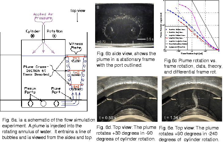
4.3. The Fluid Flow Simulation of the Sodium ExperimentWe have simulated the α and Ω flow fields in water (Beckley & Colgate 1998). Figure 6(a) is the schematic showing the two differentially rotating cylinders and the pulsed plumes. Figure 6(b) shows a side view of the pulsed, rising and expanding plume outlined by a line of bubbles (like an entrained line of force). Figure 6(c) is a plot of plume rotation angle vs frame rotation angle from solid-body and differential frame rotation data and plume rotation theory. Figures 6(d) and 6(e) are a time sequence of the top view of a rising plume in a rotating frame showing the progressive rotation of the plume angle as needed for the generation of the coherent helicity.
Figure 6: Figure 6 shows a composite of the
flow visualization experiment where a rising plume in a rotating
frame, Fig. 6(a), is viewed from the side, Fig. 6(b), and
top, Figs. 6(d) & 6(e). The resulting angle of differential
plume rotation is measured and plotted as a function of frame
rotation, Fig. 6(c). (see http://physics.nmt.edu/~dynamo/)
4.4. The Simulation of the α - Ω DynamoPariev et al. 2000 have performed kinematic dynamo calculations using a 3-D vector potential code for the evolution of the magnetic field as a function of time by a time-dependent velocity flow field. The α - Ω dynamo, by its nature, is 3-D and non axisymmetric, but the primary flow is circular, Couette or Keplerian, with occasional non-axisymmetric flows or plumes. Thus the code is written in cylindrical coordinates, analogous to both the astrophysical or experimental geometries. We use the vector potential for the calculated quantity, because then ∇ · B = 0 at all times and no periodic calculational "cleaning" of ∇ · B has to be performed. The boundary condition is perfectly conducting so that the flux through the boundary must be constant in time. This allows for an initial poloidal bias field, but thereafter the flux through the boundary must remain constant. Therefore all the flux generated by a dynamo solution must remain within the box. Since this is not the case for either the experiment or the astrophysical circumstance, we must simulate problems with the walls as far removed from the region of action as possible. A non-conduction boundary condition requires the solution of the external potential field at each time step and is planned for the future.
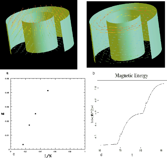
Figure 7: Figure 7 shows the dynamo
calculations of Pariev et al. 2000 with an initial bias poloidal
field, Fig. 7(a), with radial and axial components. This field
is wrapped up by the differential rotation in the liquid sodium,
Fig. 7(b). A pair of plumes every N revolutions gives
rise to a gain Fig. 7(c) that shows marginal gain at a pair of
plumes each 6 revolutions. The exponentiating field energy is shown in
Fig. 7(d) where N=3 and the pulsed increase in field
energy is seen for each plume.
Figure 7(a) shows the cylindrical geometry with a radial initial poloidal field, a potential field as will be imposed by external coils. Differential rotation, Couette flow, Ω ∝ 1/R2, is imposed with a value of resistivity such that Rm,Ω = (R0 - R1)ν0/ηNa = 120. Figure 7(b) shows the poloidal field wrapped up into a toroidal field with a ratio shown in Fig. 7(c) as a function of radius. We expect to measure these same quantities in the Ω-Phase experiment. Simulations show the fields when a pair of symmetric, cylindrical plumes are injected vertically of initial radius, rplume,0 = R0 / 6 or 2rplume,0 = dplume,0 = ( 2/3)(R0 - R1 ). For positive dynamo gain, ≅0.12 per revolution, this pair of plumes is pulsed once every 3 turns with a vertical velocity of vplume,z = 0.5 v0. The simulated plumes are cylinders of constant radius that untwist or rotate relative to the frame such that their change in angle is π/2 radians when the background fluid at the plume radius has rotated π radians. A marginal positive dynamo gain of 0.01 per turn is observed for a pair of plumes per 4 revolutions. In the experiment we expect the plumes to diverge as they rise and rotate more rapidly when they strike the end wall as observed in the fluid visualization experiment. As a consequence of both these effects, the experimental plumes should create greater helicity than in the simulations. Other (unknown) effects will surely decrease the dynamo gain. We are therefore planning the experiment to meet these conditions.
5. PROPOSED WORK5.1. Design of the Experiment and FeasibilityThis section is more detailed than would be of general interest, but our last proposal was firmly criticized for lack of detailed engineering calculations of the strength of the vessel and the power to drive it to the necessary magnetic Reynolds number. Consequently we calculate the pressure and power as a function of Rm,α & Rm,Ω and then use an engineering stress analysis to demonstrate that our constructed experiment, Figs. 3, meets the criteria of the kinematic dynamo calculations above. These criteria are Rm,α = 20 and Rm,Ω = 120 with one pair of plumes per three turns. The size, power and cost of the experiment are are related to these desired values of Rm. We have chosen cylindrical geometry as the closest approximation to the black hole accretion disk geometry and the most convenient for construction. Spherical geometry would simulate stellar dynamos and make easier the calculation of resistive boundary conditions. We have also chosen Couette flow to minimize the fluid flow dissipation rate and maximize the shear or differential rotation for the Ω flow. For a given desired Rm we will calculate how the pressure and power varies as a function of R0, namely the choice of a size. 5.1.1. Centrifugal PressureThe centrifugal pressure in the fluid sodium determines the required strength of the vessel wall. For Couette flow, Ω ∝ 1/R2 or ν ∝ 1/R and the fluid pressure becomes:
when R1 / R0 = 1/2. This ratio is chosen to maximize the annular space, R0 - R1 for the dynamo and hence maximize Rm,Ω = (R0 - R1)ν0/ηNa, yet minimize the acceleration and hence the wall stress at R1. For rigid-body rotation and the thin-wall approximation, the inner wall stress becomes
Therefore for the ratio R1 / R0 = 1/2, the inner wall stress will be ×8 the outer wall stress without fluid pressure. This then allows the outer wall to support primarily the fluid centrifugal pressure rather than its own centrifugal stress, whereas the inner cylinder supports just its own centrifugal stress. Thus for a limiting wall stress or pressure and a desired Rm,Ω, the stress decreases as 1/R02 and so there is a large advantage to size. With this in mind we chose the largest size for which there exists standard bearings, drive belts, mounts, surplus materials, materials handling, and local machine tools for finishing. This size is R0 = 30 cm, and Z0 = R0 = 30 cm. We next calculate the achievable Rm,Ω and Rm,α within the envelope of wall stress and power and compare the results with dynamo calculations. 5.1.2. Power RequirementsThe power required to drive the Ω flow is more complicated to estimate because the process of fluid dissipation is less well known in the particular limits of this experiment. We assume the Couette flow is absolutely stable and so the dissipation within the bulk of the fluid depends only on departures from ideal Couette flow. The primary departure is at the end walls where an Eckman layer forms (Batchelor 1999) of thickness ΔZ ≅ Z0Rfluid,Ω-1/2. In our experiment the fluid Reynolds number is Rfluid,Ω = (R0 - R1)νCouette/μNa = Rm,Ω(ηNa/μNa) = 9 × 10⁶, where Rm,Ω = 120, ηNa = 750 cm2s-1 and μNa = 10-2 cm2s-1. With Z0 = R0, the thickness of an Eckman layer becomes ΔEckman=(R0/2)Rfluid,Ω-1/2≅7×10-4. The radial flow velocity within the Eckman layers will be νEckman ≅ νΩ/2 because the flow is dissipative. Thus the Reynolds number of the flow within the Eckman layer becomes Rfluid,Eckman = Rfluid,Ω1/2/2 ≅ 1.4 × 10³. The flow at this Reynolds number is within the transition to turbulence and so we expect a larger effective viscosity than μNa = 0.01 and thus a larger thickness, Rturbulent,Eckman > Rfluid,Eckman. Recognizing this uncertainty, the power becomes the kinetic energy dissipated in the fluid flow in a cross-sectional area of 2πRΔEckman. The change in specific kinetic energy occurs between the Couette flow, vCouette2 /2 and the wall at v02(R/R0)2/ 2. Then the energy loss in two layers becomes
This power is unrealistically small. It implies a spin-down time of
Thus the spin down time corresponds to a number of turns of
The power predicted is unrealistically small and the
number of turns for spin down is similarly unrealistically large.
The Eckman flow will be broken up in a complicated fashion by the
jet ports in one of the end plates, and so a more realistic
estimate of the power required is times ten larger, or 12 kW,
which in turn is modest. The scaling with Rm,Ω of
Eq. (3) becomes power Similarly the plume power is small. The area of two plumes is Aplume = 2πrplume,02 = 2πR02(rplume,02/R02), and so the plume power becomes
For vplume = v0/2, nplumes/turn = 1/3, and rplume,0 / R0 = 1/6, we have
5.2. Engineering5.2.1. The Cylindrical Vessel
The actual design parameters are: an outer cylinder of R0 =
30.5 cm (12 in) with a wall thickness of ΔR0 = 3.2 cm
(1.25 in) and test-space length of Z0 = 30.5 cm (28 in).
Since Rm,Ω = 120 and ηNa = 750 cm2 s-1,
ν0 = 6 × 103 cm s-1. Consequently the pressure of
the liquid sodium at the wall from Eq. (1) is P0 = 54 atm or
P0 ≅ 800 psi. The thin wall cylindrical vessel under pressure is the simplest stress analysis, σhoop,Al = PNa(R0/ΔR0) = 8000 psi, (Formula (1b), Table (29), p. 448, ``Formulas for Stress and Strain'', Roark and Young 1975). Similarly there is an additional stress due to the centrifugal acceleration of the cylindrical vessel itself. In this case for aluminum with density 2.7 and again in the thin wall limit σhoop,Al ≅ ρAlν02((R0 + ΔR0)/R0) = 107 atm = 1570 psi (p. 566, ``Formulas for Stress and Strain'', Roark and Young 1975). Since this stress is also a hoop stress, it can be directly added to that from the liquid sodium to give a total hoop stress in the aluminum cylinder of 9,570 psi. The aluminum of the cylinder is 5083H3 which at a temperature of 110C has a yield strength of 32 ksi. Thus we feel that the wall stress at the maximum conditions will be 1/3 the yield strength. As an additional safety measure we expect to band the vessel with stainless steel or KevlarTM, pre-compressing the vessel by 2000 psi at an internal stress of the banding of half the yield strength of the banding. The axial stress in the cylinder is determined by the integral of the end wall pressure, Eq. (1), the force Fend divided by the circumference and the thickness,
For ρNa = 1 and R1/R0 = 1/2, the axial stress becomes
For the desired value v0 = 6000 cm/s, the axial stress becomes 220 atm = 3,300 psi. This adds vectorally to the hoop stress a small ≅10% addition. We will initially perform the tests with the thrust end-plate welded and the driven end-plate bolted using 40 grade 316SS 3/4 - 10 × 3 bolts on a 32 cm (12.62 in) bolt circle. The resulting bolt stress becomes 40 ksi, an acceptable value. 5.2.2. The End Plates
The thrust end-plate is 6061T651 aluminum of thickness ΔZend = 3.2 cm (1.25 in), 61 cm (24 in) o.d. with an i.d. of
20.3 cm (8 in), Fig. 3(a). The driven end-plate is 5083H3
aluminum of thickness of ΔZend = 3.2 cm (1.25 in), 70
cm (27.5 in) o.d. with an i.d. of 17.8 cm (7 in), Fig. 3(b). The maximum centrifugal stress in these annular plates is given by (Formula (6), p. 567, ``Formulas for Stress and Strain'', Roark and Young 1975) as
for the conditions Rhole/Router = 1/4 and the desired velocity of v0 = 6000 cm/s. Thus the centrifugal stress in the end plates is is negligible. The bending stress due to the fluid pressure is more significant. We must consider a circular plate of outer radius Rend,outer, fixed by the cylinder and loaded with the pressure distribution of Eq. (1) from R0 to just inside R1 with the inner edge guided. The bolting or welding to the cylinder serves the purpose of "fixing" the outer radius with the inner radius guided by the flanges and no axial confinement by the bearings. Formula (3f) of Table (24), p. 345 of ``Formulas for Stress and Strain'', Roark and Young 1975 best fits this circumstance of outer edge fixed and inner edge guided with a linearly increasing pressure distribution extending from R1 to R0. This approximation is conservative relative to the quadratic distribution. The actual case is between these limits. The maximum stress in the plate then becomes
for both the driven and thrust plates where R0/ΔZend ≅ 10. Then for R0/R1 = 2, Formula (3f) gives KM<<596>>R<<439>>0 = 0.025 and KM<<597>>R<<440>>1 = 0.011. The corresponding stresses become σend,R0 = 15P0 and σend,R1 = 6.6P0. At our desired velocity of 6000 cm/s, these become σend,R0 = 8000 psi and σend,R1 = 3500 psi. Both of these stresses are modest compared to the strength of 6061T651 Al at 110 C of 32 ksi. The deflection of the plates under this load is given by
Where the plate constant, D = EAlΔZend3/(12(1 - ν2)) = 1.8 × 10⁶. Then for Ky,R1 = 7 × 10⁻⁴, the deflection on axis δZend = 3 × 10⁻³ in. This is a negligible axial deflection considering the end play in the thrust bearing and the much larger thermal expansion of ΔZthermal = ΔTL0Kthermal ≅ 0.04 cm. We recognize that this analysis is not exact, but plan to hydrostatically test the vessel, measure the deflections, and compare to these estimates. Additional strength can be added to weak points in the design later if necessary, but the major fraction of the physics is accessible at one half the planned maximum velocity and therefore at 1/4 the stress. 5.2.3. The Bearings, Dynamic Balance, and SealsThe rotating mass of the vessel and shafts is Mrotating,R0 ≅ 300 kg. We have designed the bearings of nominal size 5 in, to operate for a "normal" lifetime of 108 revolutions (4 months at 30 Hz) with a load of ×100 the rotating mass. Since the acceleration at R0 is a(R0) = 103 g, then we can expect the bearings to support an out-of-balance rotating load of 1/10 the static mass at R = R0. This is absurdly large. The mass of the base and mounts is ≅×5 the mass of the rotating apparatus or 1500 kg, so that without additional restraint, the static support and mounts will restrain an out-of-balance mass of ≅1.5 kg at R = R0. This also is an absurdly large balance error. Our electronic sensors weigh ≅100 g and we expect to balance the rotating mass to ≅10 g corresponding to an out-of-balance load of 10 kg at R = R0. Automotive crank shafts are routinely balanced to 0.01 g at R = 5 cm. For Couette flow the inner cylinder rotates at Ω1 = 4Ω0 and so the acceleration becomes a(R1) = 8 × 10³ g. This larger acceleration requires a more careful balancing, but since the inner cylinder is a single part whose mass Mrotating,R1 ≅ 20 kg or ≅ 0.06 Mrotating,R0, the degree of balance, 0.1 g at R = R1, is also feasible on an automotive crank shaft balance system. With this degree of out-of-balance mass of 10 and 0.1 g respectively and thus with an out-of-balance load of Mload = 10 kg, we expect a vibration amplitude of ΔR = 2Mloadg/(MmountΩ0,12) ≅ 2 × 10⁻⁴ cm. Since this is much smaller than the bearing clearances, we expect the vibration amplitude to be that of the rotating mass itself resulting in an amplitude of ×10 larger or ΔR = 2 × 10⁻³ cm. Again this amplitude of vibration is minor. We next consider the rotating seals. We plan to operate the experiment with a small quantity of mineral oil, ~ 10 to 100 cm3 in contact and floating above the liquid sodium. The density of oil is ρoil ≅ 0.96 ρNa and consequently floats above liquid sodium. We have performed MHD experiments in the past taking advantage of this small density difference (Colgate et al. 1960) and the oil coating avoids the requirement for using an inert gas in the handling of liquid sodium. Thus, in the rotating frame of the the experiment, the oil "floats" to the axis. We expect to adjust the quantity of oil such that the shaft seals are always bathed in oil, not sodium. This ensures that the industrial problem of seals and liquid sodium is avoided.
5.2.4. Thermal PropertiesSolid sodium is an excellent thermal conductor, ≅ 1/2 that of copper. Hence, the thermal time constant of the entire mass, heated or cooled from inside the inner cylinder by hot oil is theat = R02/Dthermal ≅ 600 s. Once the sodium is hot enough to liquefy, at 100 C, convection is rapid and the experimental mass becomes isothermal For example, the heating of 20 kW of heat or power dissipation is theat = (heat mass)/power = 2000 s or 1/2 hour. Similarly an experimental run lasting 10 seconds at high power, e.g. 40 kW, will heat the whole apparatus by 1 deg C without cooling, an acceptable small value. Cooling by windage will be comparable. 5.3. Theory: Astrophysical ApplicationsAlong with the proof-of-principle of the α - Ω dynamo, the project also seeks to connect the dynamo to the physical universe. Besides the black hole accretion disk dynamo, we see a natural way to produce an astrophysical dynamo during a core collapse supernova. We propose to simulate such a dynamo using an available numerical code. Present type II supernova theory (Herant et al. 1994) predicts that a robust explosion occurs only above the forming degenerate core because of neutrino-driven large scale convection in the supernova. This large scale convection in a rotating frame is exactly the conditions necessary for the α - Ω dynamo. In fact, such a dynamo may be necessary for the following reason: Ultra strong magnetic fields ~1012 G are a fundamentally accepted part of neutron star/pulsar theory, but their origin and extraordinary uniformity among pulsars is hard to explain. The standard explanation requires an initial field of 108 G in the core of the supernova progenitor star for every case, which seems unrealistic.
We believe that a natural way to arrive at the ubiquitous field of
~1012 G inferred from the An additional consequence of the dynamo is to generate field with high-order multipole moments at the neutron star's surface. Such multipoles could facilitate the modeling of emission profiles which don't fit the simple dipole model (Eilek et al. 2000). The simulations of the supernova core collapse dynamo will use the existing code, described in Section 4.4 Pariev et al. 2000. The current version of the code assumes a boundary which is perfectly conducting. A necessary modification of the code, to include non-conducting boundary conditions, requires solution of the external potential field, which is simpler in spherical geometry and will be undertaken as part of the proposed work.
6. SAFETYThe fear of sodium may have been fueled by youthful indiscretions in the chemistry lab, yet metallic sodium is a major industrial chemical. Industry has used millions of tons of metallic sodium, shipped in thousands of railroad tank cars of greater than 50 tons each. These tank cars are surrounded by an oil jacket for heating. This is accomplished with negligible risk to the public as determined by DOT. The mass of sodium in each tank car is more than several hundred times the mass of sodium used in our experiment. Sodium is also shipped in barrel size containers where the container is non-returnable. Liquid sodium is the lowest density, high conductivity fluid that is biologically benign. There is a vast difference between using sodium at 600 deg C as a fast reactor coolant and using sodium at 110 C as in this experiment. Much of the high end technology of liquid sodium was developed for the high temperature coolant purpose. Those facilities, built on a massive scale and now surplus, have been used for two recent successful sodium dynamo experiments in East Germany and Latvia (Gailitis et al. 2000; Busse et al. 1996; Rädler et al. 1988). These experiments were performed in immense halls for full containment of a liquid sodium equipment failure. We believe that this scale, cost, and the equipment is an unnecessary burden. We expect to test a different dynamo flow field in more modern and modest equipment, developed in the laboratory and easily moved periodically to and from an adjacent, proven testing facility for high-energy materials (whenever testing with liquid sodium). These tests will be performed in a safety test cell and remotely. This facility, the Energetic Material Research and Testing Center (EMRTC) has a 60 year history of tens of thousands of accident free high explosive tests. Sodium is very safe compared to HE; it cannot detonate. Finally one of us (Colgate 1955) has had extensive hands-on use of liquid sodium in laboratory experiments for determining MHD stability for fusion confinement. The experiment will be perfomed in compliance with Federal, State, Industry and Institutional safety practices and procedures involving the receipt, storage, handling, disposition and use of sodium metal. Because of length, the Safety Practices, Procedures and Compliance are presented in our web-site http://physics.nmt.edu/~dynamo/. A removable, electrically heated, safety shield will surround the cylindrical vessel and will be useed whenever the apparatus is rotated and filled with either oil or sodium. This will confine any dynamic sodium loss and absorb the kinetic energy and containment of disrupted parts should a mechanical failure occur. Operating procedures will include: safety training, balancing, hydrostatic pressure testing with oil, pressure deflection checks, calibration of pressure sensors, relief-valve testing and setting, and thermal controls. Because of length, these Operating Procedures are also presented in our web-site for the project: http://physics.nmt.edu/~dynamo/
7. ADMINISTRATIVE JUSTIFICATIONS1) The sodium experiments will be performed at the Energetic Materials Research and Testing Center (EMRTC), a division of NMIMT, Socorro, NM, where explosives and armaments have been tested and developed since WWII. Many students, graduate and undergraduate, work at EMRTC, so that strong student participation has been a tradition for 58 years. Thus education, safety, and health are fundamental to the operation as well as the basic engineering and experimental expertise.
8. PERSONNELStirling Colgate is an astrophysicist. He holds an associate position (retired) at LANL and is an Adjunct Professor of Physics at NMIMT. He has had extensive past experience as an experimentalist in the plasma physics of fusion and sodium MHD experiments. His experience with liquid and solid sodium experiments include four MHD experiments performed by Colgate (1954, 1955) and Colgate, Furth, & Halliday (1960). He also has an extensive reputation in theoretical astrophysics. Funding request is for travel only.
John Finn is a staff member in T-15, theoretical plasma physics at LANL. He has published in dynamo theory, written kinematic dynamo codes, and helped direct Pariev in writing the kinematic dynamo code. (LANL support) Vladimir Pariev is a graduate student at Univ. of Arizona (Jokipii and Levy professor) who has spent summers at LANL, published in GR of black holes, and written and tested the α - Ω code. This fall he will continue with his theoretical dissertation on the experimental and galactic dynamos under the direction of Finn and Colgate. (LANL support) Hui Li is a member of group X-6 who has specialized in x-ray and gamma ray emission mechanisms and spectra. He will be instrumental in the astrophysical interpretation of the saturated dynamo and AGN. He has also led the effort on the Rossby vortex mechanism of accretion disks and thus the hydrodynamic basis of the galactic dynamo. (LANL support)
References
About this document ...This document was generated using the LaTeX2HTML translator Version 97.1 (release) (July 13th, 1997) Copyright © 1993, 1994, 1995, 1996, 1997, Nikos Drakos, Computer Based Learning Unit, University of Leeds.
This document was posted by Howard Beckley on 25 April 2001
|